Managing SnapReplicate™ and SNAP HA™
SnapReplicate™ provides a simple yet powerful means of defining a replication relationship between two SoftNAS controllers - the source node and the target node.
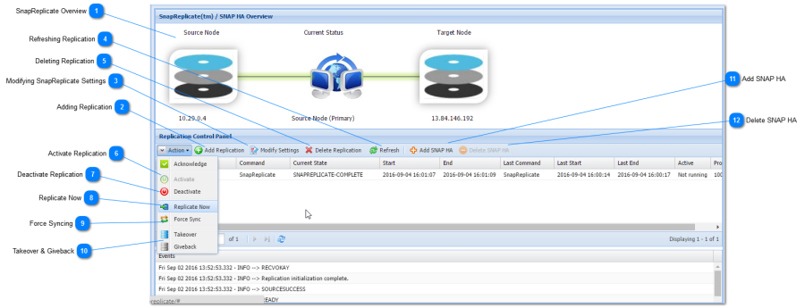
SnapReplicate Overview
SnapReplicate can be used for backup purposes, to create a hot-spare for failover and disaster recovery, and for site-to-site data transfers (e.g., region-to-region data replicas across Amazon EC2 data centers, VMware failover across data centers, etc.).
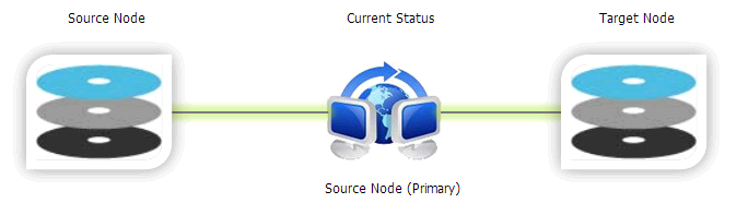
In the following example, you can see a source node and a target node. The data is always replicated from the source to the target. The Current Status shows the replication active symbol (the two computers with blue arrow), along with the green transfer indicator.
The replication relationships works both the ways. The controller can become the primary source node, to facilitate failover operation. If the source node fails or requires maintenance, then the administrator can log into SoftNAS StorageCenter on the target node, and issue a Takeover command, which will cause the target to take over the role of source. Once the source node is repaired and back operational, a Giveback command can be used to revert the control back to the original source node.
Preparing the SnapReplicate Environment
The first step in preparing a SnapReplicate deployment is to install and configure two SoftNAS controller nodes. Each node should be configured with a common set of storage pools with the same pool names.
For best results, it is recommended (but not required) that pools on both nodes be configured identically (or at least with approximately the same amount of available total storage in each pool).
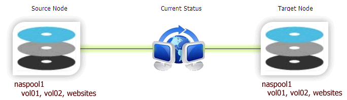
In the following example, we have a storage pool named naspool1 on both the nodes, along with three volumes: vol01, vol02 and websites. In such cases, the SnapReplicate will automatically discover the common pool named naspool1 on both nodes, along with the source pool's three volumes, and auto configure the pool and its volumes for replication. This means you do not have to create duplicate volumes (vol01, vol02, and websites) on the replication target, as SnapReplicate will perform this action.
Other important considerations for the SnapReplicate environment include:
- Network path between the nodes
- NAT and firewall paths between the nodes (you must open port 22 for SSH between the nodes)
- Network bandwidth available and whether to configure throttling to limit replication bandwidth consumption
Please note that SnapReplicate creates a secure, two-way SSH tunnel between the nodes. Unique 2048-bit RSA public/private keys are generated on each node as part of the initial setup. These keys are unique to each node and provide secure, authenticated access control between the nodes. Password-based SSH logins are disabled and not permitted (by default) between two SoftNAS nodes configured with SnapReplicate. Only PKI certificate-based authentication is allowed, and only from known hosts with pre-approved source IP addresses; i.e., the two SnapReplicate nodes (and the configured administrator on Amazon EC2).
After initial setup, SSH is used for command and control. SSH is also used (by default) as a secure data transport for authenticated, encrypted data transmission between the nodes.
Adding Replication
You will need to be prepared with the IP address (or DNS name) of the target controller node, along with the SoftNAS StorageCenter login credentials for that node.
To establish the secure SnapReplicate relationship between two SoftNAS nodes, simply follow the steps given below.
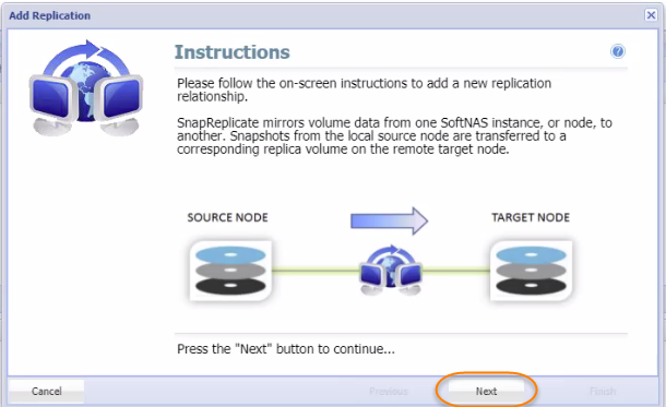
- Click the Add Replication button in the Replication Control Panel.
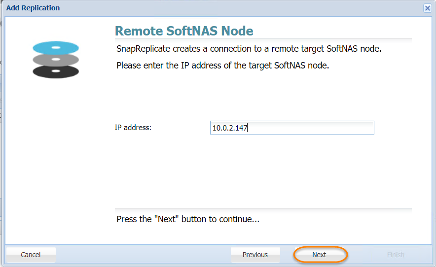
The Add Replication wizard will be displayed. - As instructed, enter the IP Address of the target SoftNAS® node and then click the Next button.
- In the next step, enter the IP address or DNS name of the remote, target SoftNAS controller node in the Hostname or IP Address text entry box.
There are two ways to set up AWS EC2 nodes for high availability. Previously, only Elastic IPs could be used. Private HA is now supported, using Virtual IPs. A Virtual IP is a HUMAN ALLOCATED IP address outside of the CIDR (Classless Inter-Domain Routing) range. For example, if you have a VPC CIDR range of 10.0.0.0/16, one can use 20.20.20.20. This will then be added to the VPC Route Table, and will be pointed to the ENI device (NIC) of one of the SoftNAS HA Nodes. A private high availability setup is recommended, as it allows you to host your HA setup entirely on an internal network, without a publicly accessible IP. In order to access your high availability EC2 cluster, an outside party would need to access your network directly, via a jumpbox, or VPN, or other solution. This is inherently more secure than a native Elastic IP configuration.
To connect the nodes, the source node must be able to connect via HTTPS to the target node (similar to how the browser user logs into StorageCenter using HTTPS). HTTPS is used to create the initial SnapReplicate configuration. Next, several SSH sessions are established to ensure two-way communications between the nodes is possible. SSH is the default protocol that is used for SnapReplicate for replication and command/control.Amazon EC2 Node:
Whether using a Virtual or Elastic IP setup to create a SnapReplicate relationship between two EC2 nodes, the source node must be able to connect via HTTPS to the target node (similar to how the browser user logs into StorageCenter using HTTPS). HTTPS is used to create the initial SnapReplicate configuration. Next, several SSH sessions are established to ensure two-way communications between the nodes is possible. SSH is the default protocol that is used for SnapReplicate for replication and command/control. When connecting two Amazon EC2 nodes, keep in mind that you will need to use the internal instance IP addresses (not the the human allocated virtual IP outside the CIDR range mentioned above, or the Elastic IP, which is a public IP). That's because the traffic gets routed internally by default between instances in EC2 by default. Be sure to put the internal IP addresses of both EC2 instances in the Security Group to enable both HTTPS and SSH communications between the two nodes.
To view the internal IP address of each node, from the EC2 console, select Instances, then select the instance - the Private IPs entry shows the instance's private IP address used for SnapReplicate.
For example:- Node 1 - Virginia, East (zone 1-a) Private IP: 10.120.1.100 (initial source node)
- Node 2: Virginia, East (zone 1-b) Private IP: 10.39.270.23 (initial target node)
Add the following Security Group entries: - SSH 10.120.1.100/32
- SSH 10.39.270.23/32
- HTTPS 10.120.1.100/32
- HTTPS 10.39.270.23/32
VMware/RHEL:
Similarly, it is important to understand your network topology and the IP addresses that will be used - internal vs. public IP addresses when connecting the nodes.- Click the Next button.
- Enter the administrator's email ID for the target node in the Remote Admin User ID text entry box.
- Enter the administrator's password for the target node in the Remote Admin Password text entry box.
- Re-enter the administrator's password for the target node to confirm the same, in the Verify Admin Password text entry box.
- Click the Next button.

- The IP address/DNS name and login credentials of the target node will be verified. If there is a problem, an error message will be displayed. Then you need to click the Previous button to make the necessary corrections and then click the Next button to continue.
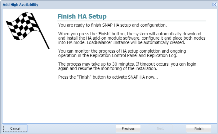
- In the next step, read the final instructions and then click the Finish button.
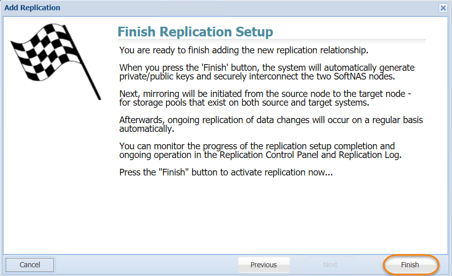
The SnapReplicate relationship between the two SoftNAS controller nodes will be established. The corresponding SyncImage of the SnapReplicate will be displayed.
The SyncImage compares the storage pools on each controller, looking for pools with the same name. For example, let's say we have a pool named "naspool1" configured on each node. Volume discovery will automatically add all volumes in "naspool1" from the source node to the replication task list.
For each volume added as a SyncImage task, that volume will be created on the target node (if it exists already, it will be deleted and re-created from scratch to ensure an exact replica will be created as a result of SyncImage). The SyncImage then proceeds to create exact replicas of the volumes on the target.
After data from the volumes on the source node is mirrored to the target, once per minute SnapReplicate transfers keep the target node hot with data block changes from the source volumes.
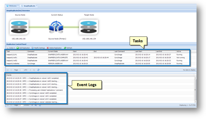
The tasks and an event log will be displayed in the SnapReplicate Control Panel section.
This indicates that your SnapReplicate relationship is established and that replication should be taking place.
Modifying SnapReplicate Settings
- To modify SnapReplicate settings, click on the Modify Settings button.
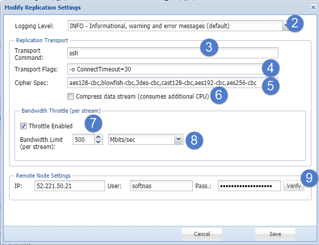
The Modify Replication Settings dialog will be displayed.
This dialog helps you to control various SnapReplicate settings. - Select the level of information to be shown in the Events Log area from the Logging Level drop down list. The available options include:
- INFO - Informational, Warning and Error Messages (Default)
- DEBUG - Debug, Informational, Warning and Error Messages (All Messages)
- WARN - Warning and Error Messages
- ERROR - Error Messages Only
- FATAL - Fatal Messages Only
- OFF - No Messages (Not Recommended)
In the Replication Transport section, enter the Linux command line string used to create a transport tunnel from source to target, in the Transport Command text entry box.
Do not modify this field unless you are sure about the changes you are making.- Enter additional flags and options for the transport command line in the Transport Flags text entry box.
- Enter the list of ciphers, in the priority order, that will be used by SSH for encryption of command & control and transport sessions, in the Cipher Spec text entry box.
- To compress the data stream, check the box in the Compress Data Stream field. This actually consumes additional CPU.
- In the Bandwidth Throttle (Per Stream) section, check the box in the Throttle Enabled field to limit the maximum network bandwidth used for each replicated volume.
- Specify the numeric value for the maximum bandwidth amount, per stream / volume and select the units (e.g., MBytes/sec, Kbits/sec, etc.) in the Bandwidth Limit (per stream) field.
- Here you can alter the connection settings used to communicate with the remote node, such as IP address, username, and password.
- Click the Save button.
The changes made to the SnapReplicate will be updated.
Refreshing Replication
You can refresh the replication and update it with the latest information. To do so, simply click the Refresh button in the toolbar.
The replication will be reloaded.
Deleting Replication
- In order to dissolve a SnapReplicate relationship between the two nodes, click the Delete Replication button.
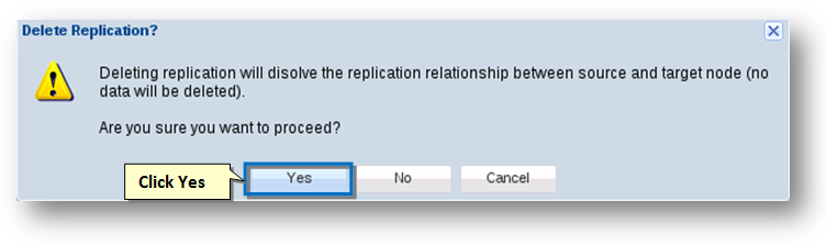
The message box asking you to confirm the dissolving of the replication relationship between the two nodes will be displayed. Click the Yes button.
The replication relationship between the source and the target nodes will be dissolved.No data is deleted. All volumes on both source and target nodes remain intact. Snapshots associated with SnapReplicate on the affected volumes are purged; otherwise, no changes to pools or volumes occurs when the replication relationship is deleted. The SSH relationship between the nodes is also dissolved, along with the PKI public/private keys and SSH login rights.
Activate Replication
You can activate replication.
- Select the replication that you want to make active.
- Click the Activate option from the Actions drop-down list.
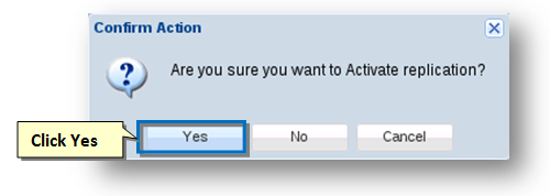
The Confirm Action message box asking you to confirm the activation of replication will be displayed. - Click the Yes button.
The replication will become active.
![]()
Deactivate Replication
You can deactivate replication.
- Select the replication that you want to deactivate.
- To do so, click the Deactivate option from the Actions drop down list.
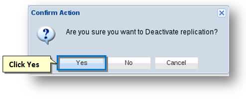
The Confirm Action message box asking you to confirm the deactivation of replication will be displayed. - Click the Yes button.
The replication will be deactivated.
![]()
About NAT and Firewalls
The SnapReplicate attempts to automatically discover the proper return path from the target node to the source. It does this on the target by analyzing the IP address of the SoftNAS StorageCenter webserver involved in establishing the relationship phase.
Consider the following scenarios.
Scenario 1 - Same data center deploymentWhen deployed in the same data center, the IP addresses will likely be locally routable, with no firewall between the controllers.
Scenario 2 - Different data center deploymentWhen the source and target are deployed in different data centers, each node will exist on different networks separated by several layers of firewalls. To determine its return path (from target-to-source), the automated setup process will use the source data center's public IP address. For example:
source node ------ Data Center 1 ------ Firewall 1------ Internet/cloud ------ Firewall 2------ Data Center 2 ------ target node
172.16.1.100 ==> 172.16.1.0/24 ==> NAT ==> 54.188.13.227 ==> 215.100.1.7 NAT ==> 172.16.30.0/24 ==> 172.16.30.225
The above path shows a network topology involving two data centers, connected via two firewalls using NAT. In this example, the source's IP address will appear to be 54.188.13.227, the public IP of Firewall 1. SnapReplicate on the target node will use the public IP address 54.188.13.227 to communicate from target-to-source (during a takeover, where the target takes over as source during a failover event). It is important that Firewall 1 be configured to allow SSH (port 22) inbound traffic from data center 2 public IP 215.100.1.7, and NAT route that traffic to the source node at 172.16.1.100, as shown below:
172.16.1.100 <= = 172.16.1.0/24 <= = NAT <= = 54.188.13.227 <= = 215.100.1.7 NAT <= = 172.16.30.0/24 <= = 172.16.30.225
VPN Tunnels
VPN tunnels may be used to provide added security with IPSec encapsulation of the SSH traffic (vs. opening port 22 directly on the Internet), and are highly-recommended when connecting SoftNAS nodes across data centers involving the public Internet. While the SSH transports use the strongest commercially-available PKI authentication and encryption, use of IPSec provides another layer of security and authentication that is likely required from a security policy standpoint in many environments.
WAN Deployment
SnapReplicate is intended for deployment using typical WAN links. For best results with WAN deployment, it is recommended to configure a bandwidth throttle which limits the amount of network bandwidth each stream is allowed to consume. Bandwidth is throttled on the outbound side; i.e., from source to target.
A unique stream (e.g., SSH session) is created for each SyncImage and SnapReplicate task. Each time a volume is replicated by one of these tasks, the bandwidth throttle will limit the amount of bandwidth allowed per stream.
For example, if you have 10 volumes and wish to limit the maximum WAN bandwidth consumption to 2 Mb/sec, then set a conservative per stream bandwidth to 200 Kb per stream (2 Mb / 10). If instead you know your data changes from the busiest volume no more than 2 Mb/sec worth of data changes each minute, then you can choose a more aggressive throttle setting of 2 Mb/sec for maximum burst throughput (in this case, if all 10 streams were to simultaneously experience significant change, a brief burst of up to 20 Mb/sec would be theoretically possible).
You may also wish to employ other methods of WAN bandwidth management; e.g., at the router or other network level.
What Gets Replicated
The SyncImage creates an exact replica of each configured source volume on the target. It first deletes the volume (if it exists) on the target, so be certain to choose the initial source and target nodes correctly.
The SnapReplicate keeps each target volume up to date with the latest data changes applied to the source volume. SnapReplicate runs once per minute as a cron job.
During each replication cycle (once per minute or anytime an ad-hoc Replicate Now cycle occurs), certain configuration information is also transferred from source to target, to facilitate a complete failover. Information transferred includes NFS exports and CIFS (Samba) configuration files.
Limitations
Takeover and giveback commands only affect which node is source and which is target, and the direction replication data flows between the nodes. It does not alter either node's IP address, DNS name or network identity in any way.
It is recommended to use DNS names as a means of redirecting incoming NFS, CIFS and iSCSI requests from one node to the other (which is a manual process that should be planned for and handled accordingly during a failover event).
SNAP HA™, covered below, is required to automate failover processes.
Replicate Now
Unlike Force Sync, which forces all pools to replicate across to the target node, Replicate Now will trigger a replication cycle to update recent changes.
![]()
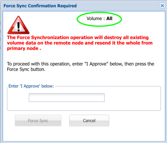
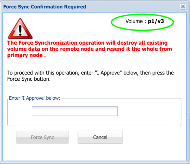
Force Syncing
You can force a sync that will retransmit all storage pools to the target node.
- To do so, click the Force Sync option from the Actions drop-down list.
The Confirm Action message box asking you to confirm the force syncing of the replication will be displayed. - Type 'I approve' into the field provided to confirm your selection.
- Click the Force Sync button.
All the storage pools are retransmitted to the target node.
Takeover & Giveback
A takeover command can be issued from the SnapReplicate control panel on the target node. For clarity, we will use node 1 to indicate the original source node and node 2 to indicate the original target node (before a takeover occurred).
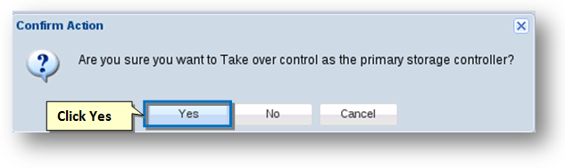
- To do so, click the Takeover option from the Actions drop-down list.
- The Confirm Action message box asking you to confirm the takeover control as the primary storage controller will be displayed.
- Click the Yes button.
When a takeover is issued from at the target node, the following occurs:- The target node 2 configures itself as the new source node, assuming all duties of the source.
- The target applies the saved configuration changes (NFS exports, CIFS and iSCSI configs, etc.) and then restarts the affected services (NFS, Samba, iSCSI) with the proper configuration. This enables the target to begin serving storage requests as if it was the former source controller.
- The new source node 2 will reset its replicate state back to a start state, which means when the target node 1 (the former source node) comes back online, replication will start over with a fresh SyncImage, followed by incremental SnapReplicate cycles once per minute, from node 2 to node 1. This will automatically re-synchronize the two nodes. If you want to manually control when re-synchronization from node 2 to node 1 occurs, then place node 2 into a deactivated state using the Deactivate command immediately following a successful takeover.
If configuring a highly available pair of instances using SNAP HA, our DeltaSync™ feature will improve replication performance by ensuring that subsequent replications will no longer start over with a fresh SyncImage, but will instead replicate only changes made since the last replication, saving significant time and data transfer costs. - A takeover timestamp was stored on the target node 2 at the time the takeover was initiated. This timestamp is used to inform the old source node 1 (which may have failed) of the takeover event. When the failed source node 1 is reactivated, it will see the takeover timestamp of node 2, which took control, and node 1 will assume the role of target appropriately.
Once the node 1 is repaired and back online, to fail back to the original node 1, use the Giveback command from node 2.
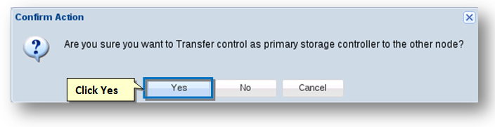
- To do so, click the Giveback option from the Actions drop-down list.
The Confirm Action message box asking you to confirm the transfer control as the primary storage controller to the other node will be displayed. - Click the Yes button.
Alternatively, you can issue a Takeover command from node 1, which will cause node 1 to assume its original duties as the primary source node.
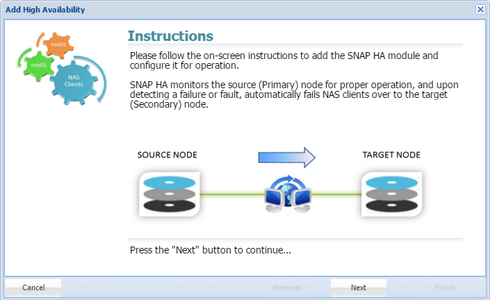
Add SNAP HA
Once a SnapReplicate pairing is established, SNAP HA can be implemented. SnapReplicate established easy manual failover, including forced synchronization and manual takeovers and givebacks. SNAP HA establishes a heartbeat which will trigger automated failover, ensuring that your dataset is protected.
![]()
- Clicking Add SNAP HA will trigger the following wizard. Click Next.
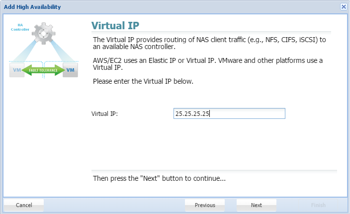
- Provide a Virtual IP. This is a human-configured (chosen by you) IP address. It must be outside the CIDR block of the two SoftNAS instance IP addresses.
Delete SNAP HA
To remove the SNAP HA relationship, click here, and accept the prompts. Unless SNAP HA is active, this option will be grayed out.
![]()
- Click Finish. Your Snap HA pairing will be complete.